BarrettHand BH8-280/282 Kinematics, joint ranges, conversion factors
Finger Drivetrain and TorqueSwitch™
It is easiest to understand Barrett's patented TorqueSwitch™ mechanism by first understanding the operation of the BarrettHand finger assembly. Figure 1 shows a single finger, including all critical drive elements, with the motor windings and rest of the hand hidden.

Figure 1 - Single BarrettHand Finger Assembly
Figure 2 is a close-up of the drive elements in the finger. During normal operation, the 16-tooth motor pinion (gray) drives both the 30-tooth distal (yellow) and 40-tooth proximal (blue) gears, which transmit power through their respective right-handed, single-start worms (red and green) and into two 50-tooth worm gears (orange and purple). The proximal worm gear (purple) is tied directly to the proximal link with six screws, whereas the distal gear (orange) connects to the distal link via mechanical cables. The net result is a motion ratio of 125:1 for the motor shaft to proximal joint position and a 93.75:1 reduction for the motor shaft to distal joint position. Also, note the two magnets (light blue) and their associated Hall-array sensors (black) at the ends of the motor shaft and worm shaft. The magnets are magnetized N/S radially, rather than axially, which allows the Puck (motor controller) to determine the position of both joints in the finger via the Hall-array sensors.

Figure 2 - BarrettHand Finger Drive Elements
The connection between the proximal worm (green), the belleville washers (pink) and the proximal gear (blue) is the critical part of this assembly that makes the TorqueSwitch™ work. The proximal gear is internally threaded, and rides on right-handed threads cut into the worm shaft, while the belleville washers are compressed between the side of the gear and a shoulder on the shaft. The compressed bellevilles create Coulomb friction in the assembly that holds the gear stationary relative to the worm.
When the proximal link contacts a surface, the resultant torque in the worm causes the gear to "break away" from the Coulomb friction and wind off the washers along the shaft. Figures 3 through 5 show this process.

Figure 3 - Finger drivetrain pre-breakaway
The worm and proximal gear rotate together at first, linked across the belleville washers via Coulomb friction.

Figure 4 - Proximal gear winding off bellevilles
When the proximal link encounters adequate resistance torque, the friction breaks away and the proximal gear winds off the belleville washers. From this point forward, the proximal link remains locked in place.

Figure 5 - Finger drivetrain post-breakaway
The proximal gear then winds up the worm shaft, directing motor torque to drive the distal link. The threaded shaft is long enough to allow full range-of-motion for the distal link in any scenario. All motor torque is directed to the distal link until the bellevilles are re-engaged by reversing the motor.
The TorqueSwitch™ is reset by opening the finger. First, the distal link will open as the proximal gear winds along the shaft, then drive the proximal gear against the belleville washers, re-engaging the clutch and causing the proximal link to open with the distal link. When the proximal link encounters a resistive force, such as its joint stop, the proximal gear will compress the bellevilles, preloading the system to a programmable level (Puck parameter "OT").
Figure 6 can be used to set OT (the factory default is 0). The force shown in this graph is applied to an object held about half way up the proximal link when the breakaway torque is reached. In other words, it is a measure of how hard the proximal links are grasping when the torque switch activates. Because of variance in the coefficient of friction, some adjustment may be necessary for your application.

Figure 6 - Breakaway Force Curve
To control how much force is applied to an object being grasped without sensor feedback such as finger-tip torque sensors (strain gauges) or tactile sensors, the MT property must be used. Please see Figure 7 to see how MT and finger torque are related:

Figure 7 - Motor Torque vs. Property "T"
Optional Strain Gage Joint-Torque Sensor
The strain gauges measure the torque about the outer link of each finger. If your BarrettHand includes this option, you will be able to query the SG property to get the present strain gauge value. This value is a number between 0 and 4095, corresponding roughly to a fingertip force of -2 to +2 kg. A finger without any force applied should report an SG value of around 2000 when the strain gauge option is installed.
The full SG curve is here: http://web.barrett.com/support/BarrettHand_Documentation/BH8-280_StrainGageCalibration.pdf
The HSG and LSG properties set the High Strain Gauge and Low Strain Gauge limits. For example, if you set HSG to 3000 before you issue a movement command that closes the finger, that finger will stop moving at the moment the SG value reaches 3000 (~1 kg). Likewise, if you set LSG to 1000 before you issue a movement command that opens the finger, that finger will stop moving at the moment the SG value reaches 1000 (~1 kg against the back of the finger).
The fingers also have a "self-preservation" feature. When the torque about the outer link exceeds 1.14 Nm (SG < 667 or SG > 3460), the finger will automatically drive itself to minimize the fingertip force. If you wish to disable this feature, you can set HSG to the special value of 10000. This will not change HSG, it will simply turn off self-preservation. If you want to re-enable the self-preservation feature, you can set HSG to the special value of 10001.
Spread Motion
The spreading action of fingers F1 and F2 on the BarrettHand™ increases the dexterity of the entire unit with only one additional actuator. Optimal grasp configurations can be achieved "on-the-fly" without costly tool changes associated with traditional grippers. In addition, the backdrivability built into this degree of freedom causes the BarrettHand™’s grasp shape to change in mid-grasp, creating a more stable grasp of oddly shaped target objects.
Should you wish to control the spread position of the fingers, the complete command set available to the fingers is also available for the spread, including commands for fixed-increment motion and move-to-position commands.
The sustainable torque that the spread fingers can exert continuously in a ‘pinch’ type grasp is shown in Figure 33. These are found by changing the FPG property while keeping all other properties at their defaults. For a given torque setting, larger forces can be achieved by curling F1 and/or F2 closed to the point where the contact point becomes closer to the spread axis.

Figure 33 - Pinch Grasp Torque
Forward Kinematics
The forward kinematics for the BarrettHand™ were determined using the Denavit - Hartenberg notation described in "Introduction to Robotics, Mechanics and Control 2nd Edition", John J. Craig. Each finger is considered its own manipulator and is referenced to a wrist coordinate frame in the center of the palm. Use the forward kinematics calculated in this section to determine fingertip position and orientation with respect to the palm.
![$^{i-l}T_{i} = \left[\begin{array}{cccc}
c\Theta_{i} & -s\Theta_{i} & 0 & a_{i-l}\\
s\Theta_{i}c\alpha_{i-l} & c\Theta_{i}c\alpha_{i-l} & -s\alpha_{i-l} & -s\alpha_{i-l}d_{i}\\
s\Theta_{i}s\alpha_{i-l} & c\Theta_{i}s\alpha_{i-l} & c\alpha_{i-l} & c\alpha_{i-l}d_{i}\\
0 & 0 & 0 & 1\end{array}\right]$
Where:
$a_{i-l}$ = distance from $z_{i-l}$ to $z_{i}$ measured along $x_{i-l}$
$\alpha{}_{i-l}$ = angle between $z_{i-l}$ to $z_{i}$ measured about $x_{i-l}$
$d_{i}$ = distance from ${x}_{i-l}$ to ${x}_{i}$ measured along $z_{i}$
$\theta_{i}$ = angle between $x_{i-l}$ to $x_{i}$ measured along $z_{i}$
$c\theta_{i}=cos(\theta_{i})$
$s\theta_{i}=sin(\theta_{i})$](/tracmath/5e411af89eeaee8c8504f54fa138abc0820f0375.png)
Equation 1 - Homogeneous Transform Between Frame {i-1} and {i}
The forward kinematics are determined using the following equation:
Equation 2 - Forward Kinematics from Wrist Frame to Fingertip
Table 8 is a list of the parameter values used to compute the forward kinematic transformation matrices for all of the fingers.

All of the kinematics for the BarrettHand™ are derived from the zero position. The configuration of the fingers and spread in the zero position of the BarrettHand™ is shown in Figure 36 along with the wrist coordinate frame.

Figure 36 - BarrettHand™ in Zero Position
Finger Kinematics:

Figure 37 - D-H Frame Assignment for Generalized Finger
Table 9 - D-H Link Parameters for Fingers

Where: “k” is defined as the desired finger [1,2,3].
- “r” is either [-1,1,0] for [F1,F2,F3] respectively.
- “j” is either [1,1,-1] for [F1,F2,F3] respectively.
The transforms from each axis to the next can be determined using the homogeneous transform in Equation 1 and finger link parameters in Table 9. Each of the first three link parameters are fixed and the fourth one is configuration dependent on one of the position variables Θk1, Θk2, or Θk3 for the first three joints.
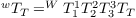
It is useful to check that the multiplication of the four transformation matrices matches for a given finger and at least one hand configuration, such as the zero position. The computed homogeneous transformation matrix from the wrist to tool frame for a finger is:
Equation 3 - Forward Kinematics Matrix for a Finger
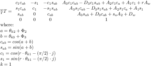
The hand configuration is determined using position feedback from the encoders. The number of encoder ticks and availability of inner link joint encoders depends on the model number of the hand. The following are the hand positions in units of radians before the TorqueSwitch™ is activated:
Notice that Θk3 will generally move 1/3 the amount of Θk2 but after the TorqueSwitch™ has been activated the inner link stops moving and all the joint torque is applied to the outer link. Users that have inner link joint position sensors will be able to determine finger joint positions at all times. For earlier hands without inner link position sensors it may be possible to estimate joint positions after detecting breakaway. This section is concerned with equations for forward kinematics and does not attempt keeping track of finger joint positions all the time. Once the outer finger link stops on hands without inner link position sensors after TorqueSwitch™ activation, the joint positions and end tip position cannot be accurately determined until the TorqueSwitch™ mechanism is reset. It may be reset by opening the finger. Refer to Appendix B for information on how to detect TorqueSwitch™ activation.
The finger end tip positions are found in the WTT matrices in the last column. Discarding the 1 in the last row, you have the Cartesian X end tip coordinate in the first row, the Y coordinate in the 2nd row, and the Z coordinate in the 3rd row.
Joint Properties
Encoder to Joint Ratios
This section describes all mechanical reductions in the 262, 280 and 282 hands as well as the ratios that go from finger and spread encoder positions to joint positions in units of radians. To find the finger or spread mechanical reduction relative to the motor use the constants in the table below. Table 10 applies to the hands before breakaway occurs. Each finger has 3 joints starting with the knuckle joint that swings the spread, the last one moves the outer link, and the one in between moves an amount proportional to the outer link until breakaway occurs. To go from motor encoder position to actual finger position for joint 2 multiply the encoder position by the corresponding joint Radians to ticks ratio. Joint 3 of the finger moves one third this amount. This transformation works before breakaway of the TorqueSwitch™ has occurred.
Table 10 - Finger and Spread Joint Ratios
| Hand Motor | Encoder(Min Ticks) | Encoder(Max ticks) | Mechanical Reduction (Joint) | Joint Radians/tick Ratio |
| 262 Finger | 0 | 17,500 | 125 (2), 375 (3) | (140°)(π/180°)/17,500 |
| 262 Spread | 0 | 3,150 | 17.5 (1) | π/3,150 |
| 280 Finger | 0 | 199,111.1 | 125 (2), 375 (3) | (140°)(π/180°)/199,111.1 |
| 280 Spread | 0 | 35,840 | 17.5 (1) | π/35,840 |
| 282 Finger | 0 | 199,111.1 | 125 (2), 375 (3) | (140°)(π/180°)/199,111.1 |
| 282 Spread | 0 | 35,840 | 17.5 (1) | π/35,840 |
The optical encoders for each of the 280 and 282 hand motors have 4096 count encoders and 262 hand motors uses a 90 line, or 360 count, encoder. Inner link encoders are the same ones used on the motor for position feedback.
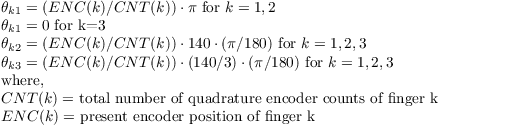
The forward kinematics from section 9.5, that are used to calculate end-tip positions, depend on the configuration of joint positions for each finger (joint 2 and joint 3) and the spread. Calculate positions in radians for each joint including spread, finger joint 2, and finger joint 3. These will be the joint positions before breakaway.
Joint 3 position can be represented more precisely if it is calculated relative to the plane of the palm plate that is accurate before and after breakaway. This position for joint 3 depends only on the model number (262, 280 or 282) of the hand where  3 is a joint 3 offset from joint 2 equal to approximately 42°.
| 262 Joint 3 Position | (π/180°) * (3 + (4/375) * ENC(k))
|
| 280 Joint 3 Position | (π/180°) * (3 + (4/375) * ENC(k) * (360/4096))
|
| 282 Joint 3 Position | (π/180°) * (3 + (4/375) * ENC(k) * (360/4096))
|
Equation 4 - Joint 3 Positions Before and After Breakaway
Note that joint 1 in the knuckle drives the outer link first through a 93.75 reduction and then a 4:1 reduction. The motor position directly determines the outer link angle with the palm plate of the hand as shown in Equation 4. During breakaway joint 2 position needs to be detected in software by using breakaway acceleration threshold for the 262 hand and then this link remains motionless as described in section 9.3. The breakaway position may be used for finding where breakaway occurred. Joint 3 position still only depends on just absolute motor position. On 280 and 282 hands, the inner-link joint position sensors may be used together with the outer link position to determine the finger positions at all times.
Joint Motion Limits
The maximum joint motion limits for the BarrettHand™ are calculated based on the zero position seen in Figure 36. Depending on the position of the spread joint, Θ11, and the objects in the grasp, the maximum joint motion limits for the finger links may vary.
The inner link, Θ12, Θ22, Θ32, has a maximum joint motion limit of 140° with no object blocking movement and Θ11 in the full close or open position. The outer link, Θ13, Θ23, Θ33, has a maximum joint motion limit of 48° when Θ11 is fully open or closed and there is no object in the grasp, as shown in Figure 38. When the spread is in any position other than full open or close, the fingers may not have the full range of motion due to interference with other fingers.

Figure 38 - Finger Joint Motion Limit Range
The spread joint, Θ11, has a maximum joint motion limit of 180° with no object blocking movement and all fingers in the full open position. If the fingers are partially closed or there is an object in the grasp, Θ11 may be restricted due to finger interference. See Figure 39.

Figure 39 - Spread Joint motion limit Range