BH8-282 Hardware setup
Initial Configuration
| Initial electrical configuration of the newer BH8-282 |

|
NOTE: If using a BarrettHand equipped with a Force/Torque Sensor, BOTH jumpers in area C should be connected. This allows power to come through the side port of the BarrettHand and feed the Force/Torque Sensor through the bottom port.
Mounting Method 1: Lab Bench Stand - demonstrated with a BH8-282 model
The Aluminum Bench Stand you received with the BarrettHand™ has been provided for convenience in programming the BarrettHand™ when a host robot arm is not available. Use the wire guides to provide strain relief to the Hand cable. The steps laid out below illustrate how to mount the Hand in the stand.
- Place the BarrettHand™ on the stand's dowel pins. Note the alignment of the BarrettHand™ relative to the wire strain relief clips to ease connection of the BarrettHand™ Cable.

- Screw on the threaded ring.

- Plug the cable into your preferred configuration. IMPORTANT - make sure you have followed Step 2 of the initial configuration instructions (top of page) to let the hand know which port to draw power from, side or bottom.
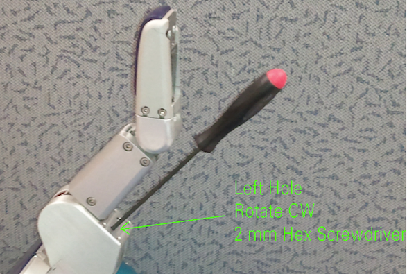
- If attaching cable to underside of hand, use the 2-mm hex wrench to open fingers 1, 2, & 3 (see here). Spread fingers to roughly 120 degrees and rest the unit on its fingertips. Tighten screws to lock cable.

- If attaching cable to underside of hand, use the 2-mm hex wrench to open fingers 1, 2, & 3 (see here). Spread fingers to roughly 120 degrees and rest the unit on its fingertips. Tighten screws to lock cable.
- Ziptie the BarrettHand™ Cable across the cable clip at an appropriate tension to provide strain relief.

Mounting Method 2: On Robot Arm
Robot-Arm Adapter
Like the Aluminum Bench Stand, the Robot Arm Adapter is made to secure the BarrettHand™ in place and to provide strain relief to the Hand cable. The Arm Adapter is fabricated for the tool-plate of your specific robot arm and is designed for low-profile, rigidity, and low weight.
To mount your BarrettHand™ on a robot, bolt the arm adapter onto the tool-plate bolt circle located at the end tip of the robot arm. Fit the BarrettHand™ onto the projecting pins on the Robot-Arm Adapter, and secure the BarrettHand™ by threading the locking ring (included with your system) onto the base of the BarrettHand™. Note that, depending on the details of your robot arm, you may need to loosen the locking ring when installing the Hand cable in the next Section.

Figure 12 - Installing an Arm Adapter.
Installing the Hand Cable on a Robot Arm
All of the power and communications for the BarrettHand™ have been consolidated into a single high-durability robot cable which has an 11-pin bayonet-style connector at the Power Supply end and a tiny 10-pin Hirose connector at the Hand end. To accommodate the complex motions of a robot arm, the BarrettHand™ Hand Cable is extremely flexible and has been designed for compatibility with both internal and external mounting schemes. When a robot arm does provide an internal channel, the cross-section of the channel is tightly constrained. Therefore the Hand cable has been made with a particularly tiny connector at one end to ease internal installation. The base of the Hand Adaptor includes an opening to accommodate direct access from an internal cable to the back of the BarrettHand™.
For external installation, plan to route the Hand Cable close to the center of each joint. Each segment will need enough slack to accommodate the most extreme motions but not so much that the cable might become snagged. Mount the cable clips to flat, dry, and clean link surfaces at strategic points along the robot arm. Clean cable clip attachment areas with alcohol before attaching via the self-adhesive backings. Place the BarrettHand™ Hand Cable loosely through the cable retaining clips on the robot and the Arm Adapter. Move the robot arm through all of its motion extremes to verify that the cable slack is adequate in each segment and that it will not snag. Once verified, tighten the cable clips to secure the cable in place.
Electrical Connections
- Place the Power Supply on a flat, secure surface anywhere between the base of the robot and the host PC (or robot controller).
- With your PC off, attach the DB-9 extension cable from your 9-pin COM Port or Peak USB to CAN adapter to the Power Supply. Barrett Technology supplies a 3-meter standard straight-through DB-9 cable, but you may purchase a longer cable if desired.
- Attach the Power Supply Line Cord into any convenient outlet and verify that it is switched OFF. Attach one end of the Hand Cable to the Power Supply and the other end into the Hand. Tighten the strain-relief screws using the Phillips screwdriver provided in the toolkit.
- Check the switches on the bottom of the hand under the access panel. For CAN operation, make sure the CAN termination is ON (SW1, #4), SW3 is set to CAN (the side with the dot), and J35/J36 is correct for which port you are using (jumper on J36 for bottom connector).
Power-Up Sequence
Once the previous steps are complete, your BH8-SERIES System is ready for use. Power up the system according to the instructions below:
- Verify the DB-9 extension cable is plugged into the desired communications port (or Peak USB to CAN adapter) and into the 9-pin connector on the back of the Power Supply.
- Verify the Hand Cable is plugged into the the back of the Power Supply and into the bottom of the BarrettHand™.
- Verify the AC line Line Cord cord is plugged into a valid power source and into the power outlet on the Power Supply.
- Turn on the host computer.
- Turn on the Power Supply. The main power switch is located on the back panel.
- The BarrettHand™ is now ready for operation.